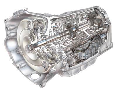
There are many “mechatronic” parts that control and protect the traditional clutches and planetary gears in modern automatic transmissions. These devices shift the gears, lock the clutches and regulate the fluid pressures.
Tool Up
When overhauling and diagnosing transmission units, you will often need special tools. Back when transmissions where purely mechanical and hydraulic, all you needed was a set of high-pressure gauges to check line pressures. You also needed a vacuum gauge to check the engine’s intake vacuum and the integrity of the vacuum modulator. But with today’s electronic controls, you need a scan tool, scope, and a multimeter.
Transmission codes and sensor data on late-model vehicles is accessed through the OBD II diagnostic connector and the Powertrain Control Module (PCM) diagnostic gateway module. But on some vehicles, the information is often found in a separate Transmission Control Module (TCM) or Body Control Module (BCM). Either way, you’ll need a scan tool to access fault codes and operating data.
A scan tool can also help you check for communication faults between the PCM and transmission controller if the vehicle has separate computers. Problems here will typically cause the transmission to go into a “limp in” mode that may lock it in 2nd gear.
Some electronic transmission problems may or may not set a fault code and turn on the MIL lamp, so it’s important to always scan the PCM or transmission module for codes if there’s a transmission-related complaint or driveability issue. Some engine sensor failures can also affect the operation of the transmission. So, these sensors should also be checked.
If you find a transmission fault code, you may have to check the resistance of a solenoid in the valve body, its operating voltage or the frequency of its control signal from the computer. This will require a digital multimeter (DMM) that can read voltage, resistance and frequency or dwell.
You’ll also need the applicable service information that includes wiring schematics and OEM diagnostic charts with test specifications for all the components that need to be checked. This kind of information can be found in OEM service manuals, on OEM websites (daily one-time access fees are typically $15 to $25), or through online technical information service providers. You should also check for any technical service bulletins (TSBs) that may be related to the transmission problem. In some cases, it may be necessary to reflash the PCM or transmission module to cure a particular fault.
Diagnostic Strategies and Transmissions
It’s often what is not displayed on the scan tool that will lead you to your final diagnosis when using a scan tool to diagnosis a drivetrain problem. The modern transmission is one of the most connected components on a vehicle. If a PCM or TCM can’t see inputs like engine speed, load or throttle position, it will assume the worst and put the transmission into a safe or limp mode.
The transmission does not have discreet sensors connected to the throttle body, crankshaft or intake manifold. Instead, the transmission shares information with the engine control and other modules in the vehicle using a serial data bus. Most vehicles manufactured after 2004 put the TCM or PCM module on the hi-speed two-wire CAN network along with BCM and ABS modules.
The topology for these networks is typically a loop. If a module is not operating, the existing modules can still communicate on the bus. When you’re using your scan tool to solve a transmission problem, you may have to look at the PIDs or datastream from the ECM or BCM to see what modules are talking on the bus.
If you can’t communicate with a transmission control module with your scan tool, look for transmission information in the connected modules. The BCM will monitor information from the TCM on gear position so it can tell the instrument cluster what gear to display for the driver.
It can also work the other way. If a TCM is not able to communicate with the ECM, looking at the transmission-related PIDs for calculated engine load, throttle position and manifold air pressure may show that the ECM is not communicating on the network.

Electronic Transmission Control Diagnostic Strategies
by
Tags:

Leave a Reply